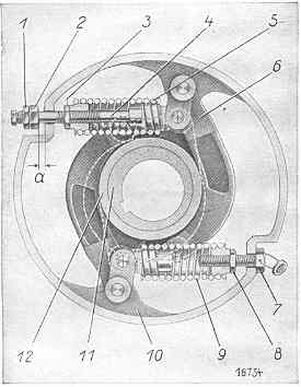
Cross Section of Governor
- Lock Nut
- Adjusting Nut
- Lock Nut
- Adjusting bolt for 850 rpm, 540 rpm, 630 rpm, 750 rpm respectively
- Governor spring for 850 rpm, 540 rpm, 630 rpm, 750 rpm respectively
- Flyweight
- Adjusting bolt for 350 rpm
- Lock nut
- Governor spring for 350 rpm
- Governor housing
- Inner (fast) eccentric
- Outer (loose) eccentric
- Dead play before action of governor
These instructions was created using notes taken from a discussion with Eric Bolwell.
It is intended as a guide only. Care should be taken when adjusting the governor. No Warrenty is given on these instructions.
To Set the Governor for S model
- Screw bolt number 4 until tight, then another 6 turns (so that it will push the spring open). For light work you may only want to try 3 turns instead of 6 turns.
- Gap "a" should be about 2 mm clearance. This can be checked by opening the weights up. There should be no clearance at "a" and 14 mm gap between the weight and flywheel hub.
- Bolt number 7 should be done up until tight then another 3 turns.
Note: for the "S" model (D1506) at idle the injector pump stoke should be 2 mm, and at maximum RPM it should be 14 mm. Other models have different injector pump settings.
Also note, that if the governor is altered, the lubricating oil pump settings should also be checked. The amount of lubricating oil used changes with engine speed. There are marks on the oilpump shaft that can be checked.
Important: if the throttle is moved past the idle mark and the engines tends to race, then bolt number 4 needs to be adjusted, lock nuts 1 and 2 should be moved in (or out) a quarter of a turn until the engines no longer races.
Table of governor adjustments taken from Nr. 53 Juli '92 issue of Der Pionier magazine
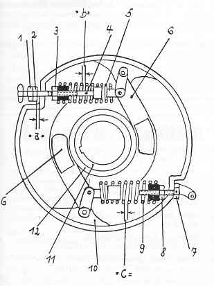
- Gegenmutter
- Einstellmutter
- Gegenmutter
- Einstellschraube fur Vollast-Drehzahl
- Reglerfeder fur Vollast-Drehzahl
- Reglergewichte
- Einstellschraube fur Leerlauf-Drehzahl
- Gegenmutter
- Reglerfeder fur Leerlauf-Drehzahl
- Reglertrommel
- Festes Excenter
- Loses Excenter
- Spielraum fur toten Gang an Vollast-Reglerfeder
- Einstellzwischenraum an Vollastreglerfeder
- Einstellzwischenraum an Leerlaufreglerfeder